Research on welding process of steel drum
Xin Qiaojuan
In the production of steel drums, the welding process is the main quality control process for steel drum production. The quality of the welding quality will directly affect the quality of the steel drums. Almost all steel drums in the world today are welded using resistance welding technology.
First, the principle of steel drum resistance welding
The resistance welding of the steel drum is to press the barrel to be tight between two electrodes, and can be heated to a molten or plastic state by electric current flowing through the barrel contact and the resistance heat generated in the adjacent area. After the power is turned off, A method of forming a strong jointed metal bond under pressure.
There are four main methods for resistance welding. Spot welding, seam welding, projection welding, butt welding. The most frequently used steel drum production is spot welding and seam welding.
1. Steel drum resistance welding characteristics
Steel drum resistance welding has two significant features:
• Use an internal heat source - use heat generated by the resistance of the weld zone to heat it.
·Pressure must be applied - Under the effect of pressure, electrical contact heating, water cooling or air cooling after the formation of contacts.
From this it can be seen that in order to obtain the proper resistance to heat, an external power supply must be provided and welding must always be performed under pressure. Therefore, the welding current IW and the electrode pressure Fw are the most basic conditions for forming a resistance welding head. As for how these two parameters change in the welding process, it depends on the material, structural characteristics, performance and welding equipment of the weldment.
2. Resistance (welding) heat generation and factors affecting heat production
The heat generated during welding can be calculated by the following formula:
Q=I2Rt... (1)Q-heat generated in the formula (J);
I - welding current (A);
R - resistance between electrodes (Q);
t - welding time (S).
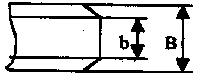
Resistance R and Factors Affecting R The resistance of the electrode in equation (1) includes the resistance Rw of the barrel itself, and the contact resistance Rw between the contact resistance Rc between the two barrels and the barrel (Fig. 1).
R = 2Rw + Rc + 2Rew... (2)
When the barrel and electrode are timed, the resistance of the barrel depends on its resistivity. Therefore, the resistivity is an important performance indicator of the welded steel drum material. A material with a high resistivity has poor thermal conductivity, and a material with a low resistivity has a good thermal conductivity. This is because the resistivity is inversely proportional to the resistance.
Changes in the electrode pressure will change the contact area between the barrel and the barrel, the barrel and the electrode, and will also affect the current line distribution (see Figure 1). As the pressure of the electrode increases, the distribution of current lines will be more dispersed, so the resistance of the barrel will decrease.

Figure 1 Resistance distribution and current lines during spot welding
When the nugget starts to form, a larger part of the current will be forced to flow from its surrounding crimp zone (plastic weld ring) due to the increased resistance of the melting zone. The melting of the zone continues and the nugget is continuously expanding. However, the diameter of the nugget is limited by the diameter of the end face of the electrode. Generally, the diameter of the nugget does not exceed 20 070, and the nugget is excessively enlarged. This will make plastic welding difficult to form due to pressure loss. Causes splashing (splashing) of molten metal.
The contact resistance R is the resistance formed by the contact between the barrel and the barrel. When both the barrel and the electrode surface are cleaned cleanly, the contact resistance only exists within the very short period of the energization and then rapidly decreases and disappears.
Even though the contact resistance is extremely short, the welding of the thin steel sheet with a short heating time still has a very significant effect on the formation of the nugget and the stability of the solder joint strength.
Rew compared to Rc, because the copper alloy (electrode material) is generally lower in resistivity and hardness than the barrel, Rew is smaller than Rc and has less influence on nugget formation.
Effect of welding current It can be seen from equation (1) that the effect of current on heat production is greater than both resistance and time. Therefore, in the welding process, it is a parameter that must be strictly controlled. The main cause of the current change is the fluctuation of the grid voltage and the change of the secondary loop impedance of the AC welder.
Effect of welding time In order to ensure the size of the nugget and the welding strength, the welding time and the welding current can complement each other within a certain range. In order to obtain a certain strength of solder joints, large currents and short times can be used; small currents and long hours can also be used. Which method is ultimately chosen depends on the properties of the weld metal, the thickness, and the power used by the welder.
Effect of Electrode Pressure The electrode pressure has a significant effect on the total resistance R between the two electrodes. With the increase of the electrode pressure, R significantly decreases. At this time, although the welding current slightly increases, it cannot affect the reduction of heat generation caused by the decrease of R. Therefore, the weld strength always decreases as the electrode pressure increases, as shown in Figure 2.
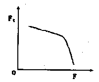
Fig. 2 Effect of electrode pressure F on the resistance strength of weld
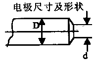
Since the contact area of ​​the electrode determines the current density, the electrical resistivity and thermal conductivity of the electrode material are related to the generation and dissipation of heat, and thus the shape and material of the electrode have a significant influence on the formation of the nugget. With the electrode tip deformation and wear, the contact area will increase and the solder joint strength will decrease.
Barrel Surface Condition Effects Oxide, dirt, oil, and other impurities on the barrel surface increase contact resistance. An excessively thick oxide layer may not allow current to pass. Local conduction, due to excessive current density, can cause splashes and surface burns. The non-uniformity of the oxide layer also affects the inconsistency of the heating of the individual solder joints, causing fluctuations in the quality of the soldering. Therefore, thoroughly cleaning the surface of the barrel is a necessary condition for ensuring good quality welding.
Second, the advantages and disadvantages of steel drum resistance welding
(A) Advantages
1. When the nugget is formed, it is always surrounded by a plastic ring, the molten metal is isolated from the air, and the metallurgical process is simple.
2. The heating time is short and the heat is concentrated. Therefore, the heat affected zone is small, and the deformation and stress are also small.
3. No welding wire, welding rod and other filler metals, and welding materials such as oxygen, acetylene, and argon are needed, and the welding cost is low.
4. The operation is simple, easy to implement mechanization and automation, and improve the working conditions.
5. High productivity, no noise and noxious gas, suitable for mass production.
(b) Disadvantages
1. There is still a lack of reliable non-destructive testing methods. Welding quality can only be checked by destructive testing of process specimens and steel drums, as well as by various monitoring technologies.
2. Point, seam welded lap joints not only increase the weight of the barrel, and due to the formation of the angle between the two plates to ask the nugget, resulting in joints with low tensile strength and fatigue strength.
3, Large equipment power, high degree of mechanization, automation, high equipment costs, maintenance is difficult, and commonly used high-power single-phase AC welder is not conducive to the normal operation of the power grid.
Three, steel drum welding process
Welding on steel drums is mainly spot welding and seam welding. Here we focus on spot welding and seam welding processes.
(I) Steel drum spot welding process
1. Spot welding general requirements
A good solder joint, from the appearance, requires a shallow, smooth transition of the surface of the pressure pit, no apparent shoulder or partial compression of the surface bulging; does not allow outside the ring or radial crack; the surface must not have melting or Adhered copper alloy. From the inside, the shape of the solder joints should be regular and uniform. The size of solder joints should meet the requirements of structure and strength. There should be no cracks in the core or beyond the specified value. The joint extensions and shrinkage holes are within the specified range. Solder joints There is no severe overheating and impermissible defects around the core.
If the defects of the solder joint are all within the specified values, the strength and quality of the structural joint are the shape and size of the solder joint. The size of the solder joint diameter directly determines the joint strength, different materials, thickness and thickness ratio, and different requirements for the solder joint diameter d. See Table 1 for details.
Table 1 Recommended sizes for spot welding and seam welding of steel drums
(mm) Solder Joint Diameter
(mm) Seam Weld Width
(mm) Minimum weld edge size
(mm) Spot welding minimum pitch
(mm) 0.3 2.5 to 3.5 2.0 to 3.0 6 5 0.5 3.0 to 4.0 2.5 to 3.5 8 7 0.8 3.5 to 4.5 3.0 to 4.0 10 11 1.0 4.0 to 5.0 3.5 to 4.5 11 12 1.2 5.0 to 6.0 4.5 to 5.5 12 13
Generally, the welding spot diameter is d = 2δ + 3 (δ is the thickness of the plate). Under the condition that the thickness of the plate edge is allowed, the diameter of the welding spot should be selected as large as possible. The weld height is expressed by the penetration rate A%, and the veneer penetration rate (see Figure 3 for symbols):
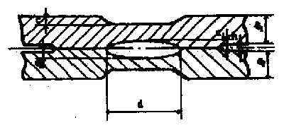
image 3
A%=[The height of the molten core on the single plate α/(the thickness of the veneer plate δ-the depth of the crush pit c)]×100%
Veneer penetration rate may be between 20% and 80%, depending on the material, thickness, and structural characteristics of the weldment. The penetration rate is too large, the melting core is close to the surface, and the surface of the barrel is prone to overheating. Deep-pit or large-scale splashing is caused, resulting in stress concentration and deteriorating the bearing performance. Considering from the core conditions, the higher the penetration rate, the greater the amount of molten metal, the shrinkage during solidification and crystallization, and the tendency to shrink holes; at the same time, due to the increase of shrinkage internal stress, cracks are likely to occur, so the penetration rate is generally taken. 40% is better, the penetration rate is too low, and the strength is low. Thin spot welding, due to heat dissipation, the use of small penetration rate, some take about IO%, and different thickness of the spot welding, the thin piece penetration rate of 10% to 20% can be.
2. Steel drum spot welding specification parameters
The quality of spot welding has a lot to do with the performance of the welder and the specification of the welding process. Welding process specification refers to the parameters that make up the welding cycle process and determine the characteristics of the spot welding specification. There are mainly welding current IW, welding pressure Fw, and energization time tw. Electrode working end face geometry, size, etc. There is a close relationship between these parameters, which can be varied within a fairly large range in order to control the welding quality. In order to correctly select the specification parameters, it is necessary to grasp the characteristics, roles, and relationships of the parameters; to understand the method of selecting the specifications.
In the simplest way, the core diameter can be used as a basis to convert known specifications into specifications under new conditions. When the materials are similar, it is advisable to use an approximate method to calculate the main specification parameters after the change of the diameter d of the solder joint, which is usually calculated according to the following relationship:
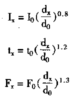
Where do, Io, t, Fo - known specification parameters;
Dx, lx, tx, Fx - specification parameters to be determined.
Table 2 shows the parameters recommended by the hard, medium, and soft specifications for low-carbon steel plates in spot welding. It can be used to compare the differences between the three specifications, as a reference for the selected parameters.
Table 2 Specification for Spot Welding of Low Carbon Steel Barrels
3. Barrel spot welding positioning
For steel drums with a volume of more than 50L, the spot welding must be performed before the barrel body is seam welded. In order to make the barrel body in the gap, it does not produce skewness or uneven edges.
For 200L steel drums, there should normally be three welding points at both ends and medium to medium, with a welding spot diameter of 6mm. It is required that the overlap be uniform and there must be no mistakes. The edge size is generally 12±1 mm. The solder joints should be firm, but scorching and burn-through must not be allowed. For steel drums below 200L, the solder joints must be at least There are two ways to position.
It is generally required that the solder joints on both sides of the barrel should not be too close to the edge to prevent the impact of the flange and the quality of the seal.
(II) Steel tank seam welding process
1. Steel barrel seam welding characteristics
Common seam welds consist of one weld. According to different degrees of core melting overlap, can be divided into rolling spot welding or gas tight seam welding. Seam welding of steel drums is hermetic welding. The formation of each joint of the composition of I gas tight seam welding and spot welding.
2. Barrel seam welding general requirements
The formation of seam welded joints is essentially the same as spot welding, and so factors affecting the quality of welding are similar.
Table 3 shows the specifications used for seam welding of barrels of low carbon steel plates.
Taking the 200L steel barrel as an example, the general steel is: No. 08 high quality carbon steel plate, hot rolled plate or A2, A3 ordinary carbon steel cold rolled plate. The material thickness is mostly δ = 1.25mm.
When using FNl-150-5 seam welding machine for seam welding, the welding speed is 1.5 ~ 3m/min; the welding current is 14000 ~ 18000A; the electrode pressure is 2 ~ 3kg/cm2; the weld width is 5 .5 + 0.5 mm .
The technological requirement is that the two ends of the weld should be detached, but the length of the detached weld shall not exceed 3 mm, and the protruding bulge shall not be allowed. The strength of the weld shall not be lower than the tensile strength of the raw material. Welds are required to be straight and must not be flattened or pulled out of the edges, and they must not be welded or cracked. The appearance of the weld should be uniform and there should be no blistering, splintering, burning or galling.
Fourth, the characteristics of spot welding, seam welding of steel barrels
The material of steel drums is mostly low-carbon steel. Low-carbon steel due to higher resistivity requires the welder power is not very large; plastic temperature zone is wide, easy to obtain due plastic deformation, does not require high electrode pressure; crystallization temperature range is narrow, high temperature plasticity is good, linear expansion coefficient is not Very high, so the tendency of hot cracks is small; Carbon and trace elements are low, no high melting point oxides, quenching organizations or inclusions generally do not appear. Therefore, there is no need to adopt complicated technological measures in spot welding and seam welding, and the welding quality is good. However, when cold-rolled low-carbon steel sheets are spotted with soft gauges, the heat-affected zone around the core will be expanded due to prolonged heating, and the grain growth and softening zone will be obvious. Therefore, when the joint strength is required to be high, it should not be adopted. Long pulse time heating. Hot-rolled low-carbon steel sheet has a thick oxide scale on the surface. If the cleaning is poor, the electrode may stick to the surface of the barrel. During the heating and expansion of the material, a deep pressure pit may be formed. When the electrode is raised after welding, the adhesion may be caused by adhesion. The pull-out of the electrode tip causes the cooling water to seep out and seriously affects the surface quality of the weldment and the life of the electrode. Therefore, the oxide scale should be carefully cleaned. The anti-rust oil on the surface of the cold-rolled steel sheet can be squeezed out of the welding point in the spot welding, generally does not affect the welding quality, and may not be cleaned. However, when the oil is applied too thick, it must be wiped so as not to increase the electrode loss due to the impurities in the oil entering the welding area. Seam welding should be carried out by surface cleaning (edging), otherwise there will be air holes, cracks, affecting the weld tightness.
Table 2 and Table 3 of specifications for spot welding and seam welding of low-carbon steel thin buckets.
Table 3 Specification for seam welding of low carbon steel drums
In the table, the diameter of the solder joint is determined according to the thickness of the board, that is, d=aδ. The degree of hardness and hardness of the coefficient a according to the specifications used are respectively 5, 5.6, and 6 (a large diameter coefficient is selected for the soft specification). The electrodes are mostly conical, and the diameter of the working end face is close to the diameter of the core. The energization time tw is proportional to the plate thickness 8 and the current density j is inversely proportional to the plate thickness 8 5 . The electrode pressure Fw should be referenced to the welding current IW, and the appropriate value should be chosen so that the Fw of the production splash is the best value. If Fw is too large, the size of the core to be melted will be too small, so that the enlarged plastic ring participates in the stress, resulting in a decrease in the strength and an increase in the volatility.
The specification of spot welding before seam welding is smaller than that of the official spot welding specification. Positioning spot welding is not more than 1mm away from the weld axis.
The welding speed of low-carbon steel seam welding is generally 1.5 m/min. If the welding process is fully automated, there is no need to manually control the position of the weld. When the capacity of the welding machine is sufficient, a welding speed of 2 to 3 m/min can also be used. When the weldment thickness increases, the welding speed should be reduced to ensure the core quality and penetration rate.
Steel drum materials are also often used galvanized steel, tin plated steel. The main problem in spot welding is that the surface layer is easy to destroy, loses the effect of the original coating layer, the electrode is easy to adhere to the surface layer of the plate, and the electrode life is short; the airtightness is not easily ensured during seam welding.
Since the melting point of zinc is only 692K, during the spot welding, the melting range of the zinc layer on the contact surface between the plates is wider than the original engine contact range between the plates. The coating layer of the welding zone melts and the extruded zinc melts with the area around the welding zone exceeding 692K. The zinc is squeezed into the board seam at the same time, forming a good conduction condition between the two boards, the current field is expanded, and the current density at the contact surface is greatly reduced. When the core diameter is in a critical state, the current fluctuates slightly and incomplete penetration occurs. From this point of view, when spot welding the coated steel plate, the current Iwo should be increased and the lower the melting point of the coating, the larger the Iw should be. In order to break through the coating layer so that the contact surface has good contact during spot welding and the melted coating is squeezed out of the contact surface, the electrode pressure should be increased by 20% to 25% compared to low carbon steel spot welding. The International Welding Society recommends the spot welding specification for galvanized steel in Table 4. When the power of the welding machine is insufficient, the welding of the galvanized steel plate can also be performed with a small current and a low pressure, but it is necessary to avoid the phenomenon of the diversion of the pressure and the current.
Table 4 Galvanized steel plate spot welding specification
The problem of seam welding of coated steel plates is similar to that of spot welding because of the wider melting range of the coating and the severe flow distribution, which requires more current to be welded. When the welding temperature exceeds 1173°C, the zinc element diffuses into the heat affected zone and the brittleness of the joint increases. Under certain conditions, cracks extending from the core to the heat affected zone are formed. The surface of the plate melts the zinc layer and forms Cu-Zn with the brazing wheel. The alloy increases the surface resistance of the welding wheel, making the heat dissipation more intensified, and the adhesion becomes more serious. The overheating of the surface layer further enhances the diffusion of the zinc element into the heat affected zone and expands the chance of crack formation. When the vapor of zinc in the core is precipitated from the solidified metal, pores are formed. Although the air hole has little effect on the weld tightness of the weld, it has a great influence on the crack and is the key problem in the seam welding of the steel barrel in the coating layer. In order to reduce the cracks, it is first necessary to improve the specification. Tests have shown that the penetration rate is small (10% to 20%) and the cracks and other defects are less. However, if the welding speed is high, the surface is overheated, the penetration is large, and cracks are easily generated. Generally meet the conditions of increasing the flow of the coating due to the melting of the coating layer, try to use small electricity; the welding speed should be lower, and use strong external water cooling. The wheel is driven with embossing rollers to correct and clean the roller surface at any time to maintain a predetermined roller density. Galvanized sheet seam welding specification reference table 5.
Table 5 Specification for seam welding of galvanized steel barrels
(mm) Weld wheel width
(mm) Welding speed
(m/min) welding current
(kA) Electrode pressure
(N) Welding Time (Week) Turning Off 0.6 4.5 2.5 16 3700 3 3 1.0 5.0 2.5 18 4300 3 3 1.25 5.5 2.3 19.5 4500 3 2
When other plated steel plates are welded, the problems and measures taken are similar to those of galvanized plates.
V. Analysis of defects in spot welding and seam welding of steel drums
The defects of spot welding and seam welding of steel barrels are divided into three categories: external defects of welded joints, internal defects and structural defects of welded parts.
1. External Defects The external surface of the solder joint should be smooth, free from cracks and sticky electrode metals, deep-extrusion pits, splashes, edge cracks, solder joint burnout and other external defects. The gap between the plates is generally limited to no more than 10% of the average thickness of the two outer plates, and the depth of the surface is generally not more than 10%. Common external defects of joints, their causes and improvement measures are listed in Table 6; the maximum number of defects allowed for all types of joints, including the number of allowable defects after repair, refer to Table 7.
Table 6 Common external defects and their causes in spot welding and seam welding of steel drums
During welding, the weldment and the welding wheel are inclined;
Welding speed too fast repair welding wheel;
Check the head stiffness, pre-set the inclination of the wheel;
Adjusting the welding speed 2 Soldered pits are too deep and the surface overheating is too long;
Insufficient electrode pressure;
Current over regulation;
Change the electrode taper angle;
Improve the cooling conditions 3 Local burn-through on the surface or the metal is strongly spilled. The weldment or electrode surface is not clean;
Insufficient electrode pressure, or no actual contact between the weldment and the electrode;
The electrode contact surface is not in the correct shape;
The welding speed is too fast, the welding wheel overheats to clean the weldment and the electrode surface;
Increase electrode pressure and replace worn electrodes;
Speed ​​electrode
Improve cooling conditions 4 Radial cracks on the surface of the solder joint Electrode pressure insufficient or insufficient electrode cooling adjustment specification 5 Ring surface crack current of the solder joint is too long to change the specification, taking care to eliminate the overheating factor 6 Blacking of the joint surface, destruction of the weldment by the cladding and Poor electrode surface cleaning;
Insufficient electrode power;
The power-on time is too long, the current is too large and the surface is cleaned in time;
Adjustment specifications;
Reduce the welding speed or improve the cooling conditions 7 The edge of the joint is crushed or cracked. The margin is too small and the electrode is not aligned.
The current is too large and the time is too long;
A large number of post-weld splash adjustment specifications;
Improve joint design;
Note that the electrode installation and the weldment flat placement 8 solder joints off the poor assembly;
Welded parts are misplaced during welding.
Adjust plate gap and electrode deflection
Table 7 Maximum allowable defect levels for all types of drum welded joints
Note: 1 The total number of defects / total number of solder joints: Class A connector is not more than 10%; Class B connector is not more than 15%; Class C connector is not more than 20%.
2 Cracks that extend to the surface are not allowed during seam welding.
3 The number of defects exceeding the allowable value.
2. Internal Imperfections Common internal defects in joints and their main causes of formation are summarized in Table 8 below.
Table 8 Internal defects of welded joints in drums and their causes
The electrode working surface has a large diameter;
Poor surface cleaning adjustment specifications;
Trimming electrode
Clear surface 2 cracks and shrinkage 3 Core vortex-like composition uneven power-on time is short, the electrical Han density is small, the electrode pressure is too large to adjust the specification 4 bond line into the surface oxide film to remove dirty clean, pay attention to the clean, brittle oxide film, And reduce the re-oxidation 5 ring layer pattern heating time is too long to adjust the specification 6 core offset electrode material, improper end dimensions or cooling conditions to change the electrode size, material and cooling at the same time I then;
Take other technical measures 7 excessive penetration rate of excessive penetration current, insufficient electrode voltage;
The power-on time is too long and the electrode cooling conditions are poorly adjusted.
Strengthen the cooling 8 penetration rate There is excessive metal overflow current between the board slots, the electrode pressure is insufficient;
During welding, the workpiece is uneven and tilted;
Small margin adjustment specifications;
Improve joint design;
If necessary, add a support fixture 9 brittle solder power supply time is short, the welding cycle is not reasonable adjustment specifications;
Change the thermal cycle form 10 Weld seams are not airtight Weld specifications are not stable, and the pitch is not proper;
The difference between the diameters of the upper and lower rolling disks is too large to adjust the equipment and control devices;
Change the diameter of the two rollers or the cooling conditions
3. Weldment Defects When the weldment is poorly assembled, improperly selected, or when the arm stiffness is poor, structural defects such as wrinkling, misalignment, or deformation between the plates may occur, and they may not be used when severe. The reason for its formation and improvement measures are shown in Table 9.
Table 9 Barrel welding defects and their causes
Large gaps between the plates of the weldment;
The clamping position of the weldment in the fixture is incorrect;
The arm stiffness difference pays attention to the optional barrel;
Strengthen the inspection of the assembly process;
Change the welding sequence to make the gap uniform;
Strengthen the stiffness of the arm or the electrode 2 The misalignment of the lap joint is not fixed or the position welding is not firm;
Locating point distance is too large;
The weldment is not clamped to adjust the tack weld specification, change the positioning point from the 3 joint warping deformation assembly or the positioning point distance is too large, the specification is too soft or poor cooling to change the positioning point distance and sequence;
Adjustment specifications
The internal and external defects of the joint are allowed to be repaired within a certain range. See Table 10 for common methods for repairing spot welds and seam weld head defects.
Table 10 Method for Repairing Weld Defects in Steel Tanks