Each acceleration sensor technology has its advantages and disadvantages. Before making a choice, it is very important to clarify their differences and test requirements. First and foremost, for applications that need to measure static acceleration or low-frequency acceleration (<1 Hz), or applications that require acceleration to calculate velocity and displacement, you need to select an acceleration sensor with DC response. For most engineering applications, choosing the right test tool will have a great impact on the test results. This article will help readers choose the correct acceleration sensor. Let's start with the classification and principles of sensors.
Basic acceleration sensor type
In general, there are two types of acceleration sensors: AC-responsive acceleration sensors. DC-responsive acceleration sensors serve as AC-responsive acceleration sensors. As its name suggests, its output is AC-coupled. Such sensors cannot be used to test static accelerations, such as gravitational acceleration and centrifugal acceleration. They are only suitable for measuring dynamic events. The DC-responsive acceleration sensor has a DC-coupled output and can respond to acceleration signals as low as 0 Hz. Therefore, the DC response acceleration sensor is suitable for testing both static and dynamic acceleration. It is not only the acceleration sensor with DC response that needs to be tested for static acceleration.
Acceleration, velocity, displacement
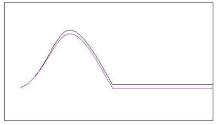
Many researches on vibration need to obtain acceleration, velocity and displacement information, which are important information that engineers need to design and verify structures. In general, acceleration provides a good reference, while velocity and displacement are the variables required for calculation. In order to calculate the speed and displacement from the acceleration, the acceleration signal output from the sensor will be integrated in the form of primary and secondary through digital or analog respectively. This may cause problems with AC-coupled sensors. To demonstrate this problem, imagine using an AC sensor to measure a wide pulse half-sine wave signal. Due to the limitation of the inherent AC RC time constant, the output of the sensor does not coincide well with the input pulse. For the same reason, at the end of the pulse, the sensor output will produce a negative zero offset. The following figure shows the relationship between the sensor output (red curve) and the wide pulse half-sinusoidal acceleration input (blue curve). This seemingly small difference in amplitude will produce a significant error after integration1. The DC response acceleration sensor has no such problem, because its output can accurately follow the slowly changing input. In actual daily applications, the input signal may not be a simple half-sinusoidal pulse, but such problems will always exist when testing any slowly changing signals with AC-coupled sensors.
Now we look at various commonly used acceleration sensor technologies.
AC response acceleration sensor The most commonly used AC response acceleration sensor uses piezoelectric elements as its sensitive unit. When there is an acceleration input, the proof mass in the sensor "moves" causing the piezoelectric element to generate a charge signal proportional to the input acceleration. From an electrical point of view, the piezoelectric element is like an active capacitor with an internal resistance of 10x9 ohms. The internal resistance and capacitance determine the RC time constant, which also determines the high-frequency pass characteristics of the sensor. For this reason, piezoelectric acceleration sensors cannot be used to measure static events. The piezoelectric element may come from nature or man-made. They have different signal conversion efficiency and linearity.
There are two types of piezoelectric acceleration sensors on the market-charge output type and voltage output type.
Charge output acceleration sensor The main piezoelectric acceleration sensor uses zirconium titanate ceramics, which has a wide operating temperature range, a wide dynamic range, and a wide frequency range (available frequency> 10kHz). The charge output type acceleration sensor encapsulates the piezoelectric ceramic in a gas-tight metal casing. Due to its ability to withstand harsh environments, it has very good durability. Due to its high impedance, the sensor needs to be used with charge amplifiers and low noise shielded cables, preferably coaxial cables. Low-noise cable means that it has low triboelectric noise, which is a kind of noise from the cable itself caused by movement. Many sensor manufacturers also provide this low-noise cable. The charge amplifier and the charge output type acceleration sensor are connected, so that the influence caused by the parallel connection of the cable capacitance and the sensor capacitance can be eliminated. With the advanced charge amplifier, the charge output acceleration sensor can easily achieve a wide dynamic response (> 120dB). Due to the wide operating temperature range of piezoelectric ceramics, some sensors can be used at -200 ° C to + 400 ° C, or even a wider temperature environment. They are particularly suitable for vibration testing at extreme temperatures, such as turbine engine monitoring.
Voltage output type acceleration sensor Another piezoelectric acceleration sensor outputs a voltage signal instead of a charge signal. This sensor contains a charge amplifier. Voltage-mode sensors are available in 3-wire type (signal, ground, power) and 2-wire type (signal / power, ground). The 2-wire type is also called an integrated circuit piezoelectric sensor (IEPE). IEPE is very popular because it can be conveniently connected by coaxial lines (2-wire, core wire and shielded wire). In this mode, the AC signal is superimposed on the DC power supply. A coupling capacitor connected in series at the output can remove the DC bias voltage of the sensor, so that only the sensor signal output is obtained. Many modern instruments provide IEPE / ICP input interface, which can be directly connected with IEPE sensors. If the IEPE power supply interface is not available, a signal amplifier with a constant current source and the IEPE sensor will be used in the first phase. A 3-wire sensor requires a separate DC power cord. Unlike the charge output type acceleration sensor, in addition to the piezoelectric ceramic element, the voltage output type acceleration sensor contains a microcircuit. The operating temperature range of the circuit limits the overall operating temperature range of the sensor, usually not exceeding 125 ° C. There are also some designs that have increased to 175 ° C, but their performance will be reduced in other aspects. Available dynamic range-Due to the extremely wide dynamic range of the piezoelectric ceramic element, the charge output type acceleration sensor is very flexible in the range definition, because its full range can be freely adjusted by the user through the remote charge amplifier. The voltage output type acceleration sensor has a predetermined full range, which is determined by the internal charge amplifier. Once it is produced by the factory, it will no longer be able to change.
DC response acceleration sensor
Two techniques are often used to make DC response acceleration sensors: capacitive piezoresistive
Capacitive
Capacitive (according to changes in acceleration, changes in capacitance caused by the proof mass) acceleration sensors are the most versatile today. There is no substitute for certain fields, such as airbags, mobile devices, etc. The high output makes this type of sensor inexpensive. But this low-cost sensor is subject to a low signal-to-noise ratio and limited dynamic range. All capacitive acceleration sensors have an internal clock. This clock (~ 500kHz) is an indispensable part of the detection circuit. Leaks often interfere with the output signal. The frequency of this noise is much higher than the frequency of the measurement signal and generally does not affect the measurement result, but it is always superimposed with the test signal. Due to the built-in amplifier chip, it generally has a 3-wire (or 4-wire differential output) interface. As long as there is DC power supply, it can work.
The working bandwidth of capacitive acceleration sensors is generally limited to a few hundred Hz, partly because of its large internal structure and heavy air damping. Capacitive acceleration sensors are suitable for measuring low-range acceleration. The upper limit is generally within 100g. In addition to these limitations, modern capacitive acceleration sensors, especially instrument-grade devices, have very good linearity and high stability. Capacitive acceleration sensors are usually suitable for onboard testing, and low cost is one reason. For low-frequency motion tests, acceleration is generally low, and they are an ideal choice. For example, vibration testing in civil engineering.
Piezoresistive
The piezoresistive acceleration sensor is another widely used DC response acceleration sensor. Unlike capacitive acceleration sensors that measure acceleration through changes in capacitance, piezoresistive acceleration sensors output acceleration signals through changes in strain resistance, which is part of the sensor's inertial sensing system. Many engineers are familiar with strain gauges and know how to measure their output. Most piezoresistive sensors are sensitive to temperature changes, so they need to compensate for their output signals inside or outside the sensor. Modern piezoresistive acceleration sensors include a dedicated integrated circuit for on-board signal processing and temperature compensation. The working frequency of the piezoresistive acceleration sensor can reach 5000Hz. Many piezoresistive acceleration sensors either use air damping (MEMS type), or
Adopt liquid damping (strain gauge type). Damping characteristics are an important factor in sensor selection. In some applications, the input mechanical vibration contains high-frequency components (or excites high-frequency response). The damped sensor can prevent itself from ringing (resonance), thereby preserving or increasing the usable dynamic range. Since the output of the piezoresistive acceleration sensor is differential pure resistance information, the signal-to-noise ratio is usually very good; its dynamic range is limited only by the quality of the DC amplifier connected later. For high acceleration shock testing, some piezoresistive acceleration sensors can measure accelerations in excess of 10,000g. Due to the wide frequency response capability. Piezoresistive acceleration sensors are suitable for pulse and crash tests, where frequency and acceleration are usually very high. As a sensor with DC response capability, the user can get speed and displacement information without integral error through its acceleration output. Piezoresistive acceleration sensors are commonly used in automotive safety testing, weapon testing, earthquake testing, etc.
summary
Each acceleration sensor technology has its advantages and disadvantages. Before making a choice, it is very important to clarify their differences and test requirements. First and foremost, for applications that need to measure static acceleration or low-frequency acceleration (<1 Hz), or applications that require acceleration to calculate velocity and displacement, you need to select an acceleration sensor with DC response. Both DC and AC-responsive acceleration sensors can measure dynamic signals. When only a quantity of dynamic signals is required, the user can do whatever he wants. Some users do not like to deal with the zero-point offset of the DC response acceleration sensor, but prefer the AC coupled, single-ended output piezoelectric acceleration sensor. Other users do not care about handling zero offsets and are accustomed to 3-wire or 4-wire interfaces, preferring load resistance self-test (shunt) and gravity acceleration self-test (2g flip) functions. They will choose a DC response acceleration sensor.
Corrugated Box
Size: customized
Printed: CMYK
Material: brown corrugated Paper Box (A,B,C,K)and white paper box (W). as below:

usage
package for shoe, cloths,eletrical products, and so on.
There are some style of corrugted box as below:
style 1: Shoe Box

style2: eletricle box

style3 canton box

stlye 4 : display box

style 5 : plane paper box

Kraft Corrugated Box,Colorful Printing Corrugated Paper,Cardboard Corrugated Paper
Shenzhen Haotuanyuan International Trading Co.,Ltd , https://www.luxurypaperbox.com