3 Solder paste printing process
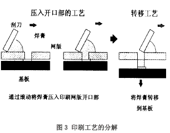
The process of solder paste printing on a printed circuit board is shown in Fig. 3, which can be divided into the process of pressing the solder paste into the opening of the printing screen and the process of transferring the solder paste pressed into the opening from the opening to the printed circuit board. Disk technology. We will be divided into considering these two processes.

3.1 The process of pressing into the opening of the printing screen
Figure 4 shows the process of pressing into the opening of the printing screen. Here, the rolling, that is, the rotation of the solder paste plays a large role. If the solder paste is moved by a squeegee, frictional force acts between the solder paste and the printed screen surface. This frictional force acts in the direction opposite to the moving direction of the solder paste, and the solder paste rotates by this frictional force, which is called a rolling phenomenon. Once the rolling phenomenon occurs, the solder paste often hits the front of the blade, changes direction, and generates pressure in the front of the blade, which is the force that presses the solder paste into the printing screen. At the same time, this scroll also has a powerful effect in lifting the scraper. Therefore, in order to achieve correct printing, it is necessary to appropriately control the force for pressing the solder paste into the opening of the printing screen and the force for lifting the blade.

The control factor of the press-in force: The optimal setting of the blade speed and the blade angle.
Squeegee speed and scraper angle are two basic factors controlling the press-in force (see Figure 5). If the squeegee speed becomes faster, the speed at which the solder paste collides with the front of the squeegee also becomes faster, and the generated force also increases. In addition, taking into account the fact that the solder paste is pressed into the opening, the time for the blade to pass through the opening, that is, the time for pressing the solder paste, becomes shorter, and the final result is that the pressure applied to the entire opening during printing does not change, and the solder paste is pressed into the opening. The number of parts has not changed, as shown in Figure 6: the horizontal axis is the speed of the blade, the vertical axis is the amount of solder paste pressed into the opening of the printing screen, and sample B shows that the amount of indentation is constant regardless of the speed of the blade. . For sample A, the squeegee speed started from 50 mm/s, and the amount of pushing was drastically decreased. This is due to the fact that the speed of the squeegee is so fast that the solder paste does not roll and slides on the surface of the printing screen. This also means that the solder paste is pressed by rolling.
Therefore, the best setting for the so-called squeegee speed is to set the solder paste so that it does not slide on the printing screen, and the setting of the rolling movement is performed. It is generally 25 to 50mm/s, QFP is 20 to 30mm/s, and ultra-fine fine pitch is about 20mm/s.


The distribution of the pressure generated at the front of the blade by the computer is shown in Figure 7. The pressure generated at the front of the doctor blade is distributed within a very narrow range of only 2-3 mm from the front of the doctor blade, so it can be said that the effect of the doctor blade angle on the generated pressure is only at the angle of the front part; and even if the angle is slightly Changes will also affect the pressure generated. Fig. 8 shows experimental results in the literature: the horizontal axis is the angle of the doctor blade, and the vertical axis is the number of solder paste pressed into the opening. The pressure generated can be changed by changing the blade angle. If the blade angle is 80 degrees or more, the solder paste of the collision blade will jump back without rolling. If no rolling occurs, no pressure will be generated and the solder paste will not be pressed into the opening of the printing screen.
Orient IRIS-CLASSIC Conventional PS Plate features the outstanding printing quality and the the largest production output with various kinds and sizes.
Feature:
High quality aluminum substrateComplex grain structure&dense oxidized layer
Excellent dot reproduction
Wide lattitude of exposure and development

Positive Conventional PS Plate
Positive Conventional PS Plate,Printing Press Plate,Classic PS Plate,Aluminum Positive Conventional PS Plate,Conventional PS Plate,Conventional Plate,PS Plate,Computer to Plate
Jiangsu Orient Printing Equipment Co.,Ltd , http://www.eastplate-iris.com